Assembling the levelshifter PCB
Introduction
In this post, I want to show you how I assembled the levelshifter PCBs (which I previously designed) with my DIY hotplate (which I also previously designed).
Applying paste
To warn you, this is actually my first time doing this.
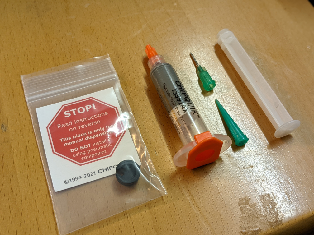
So I prepared the solder paste with the syringe and started applying it to some PCBs. I used way too much paste at first, but after a few tries I figured it out.
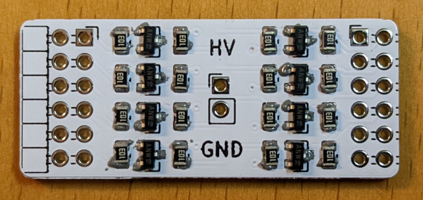
Looks good enough, doesn't it? Let's get to soldering.
Reflow Soldering Iron
A reflow profile also came with the solder paste I bought. It looks like this:
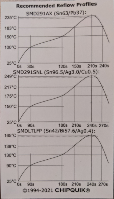
After I had programmed this reflow profile into my reflow soldering iron I placed the PCB on the iron and pressed start.
Too Hot?
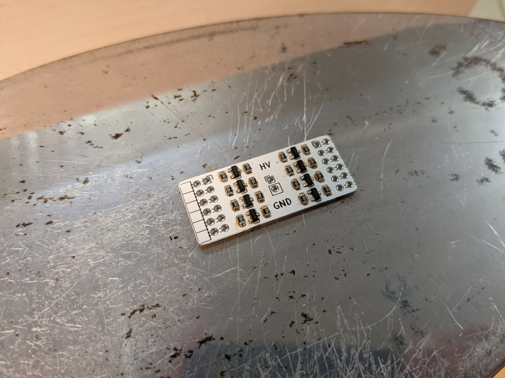
Unfortunately, the first run didn't go so well, as you can see in this picture:
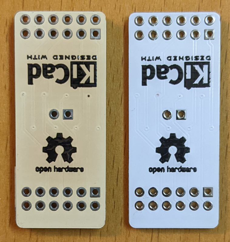
We have got a toasty PCB!
On the left side you can see the PCB from my first run, which was set to a too high temperature. On the right a fresh PCB as comparison. I may need to adjust the programming of my reflow soldering iron...
But for now I just lowered the overall temperature.
Summary
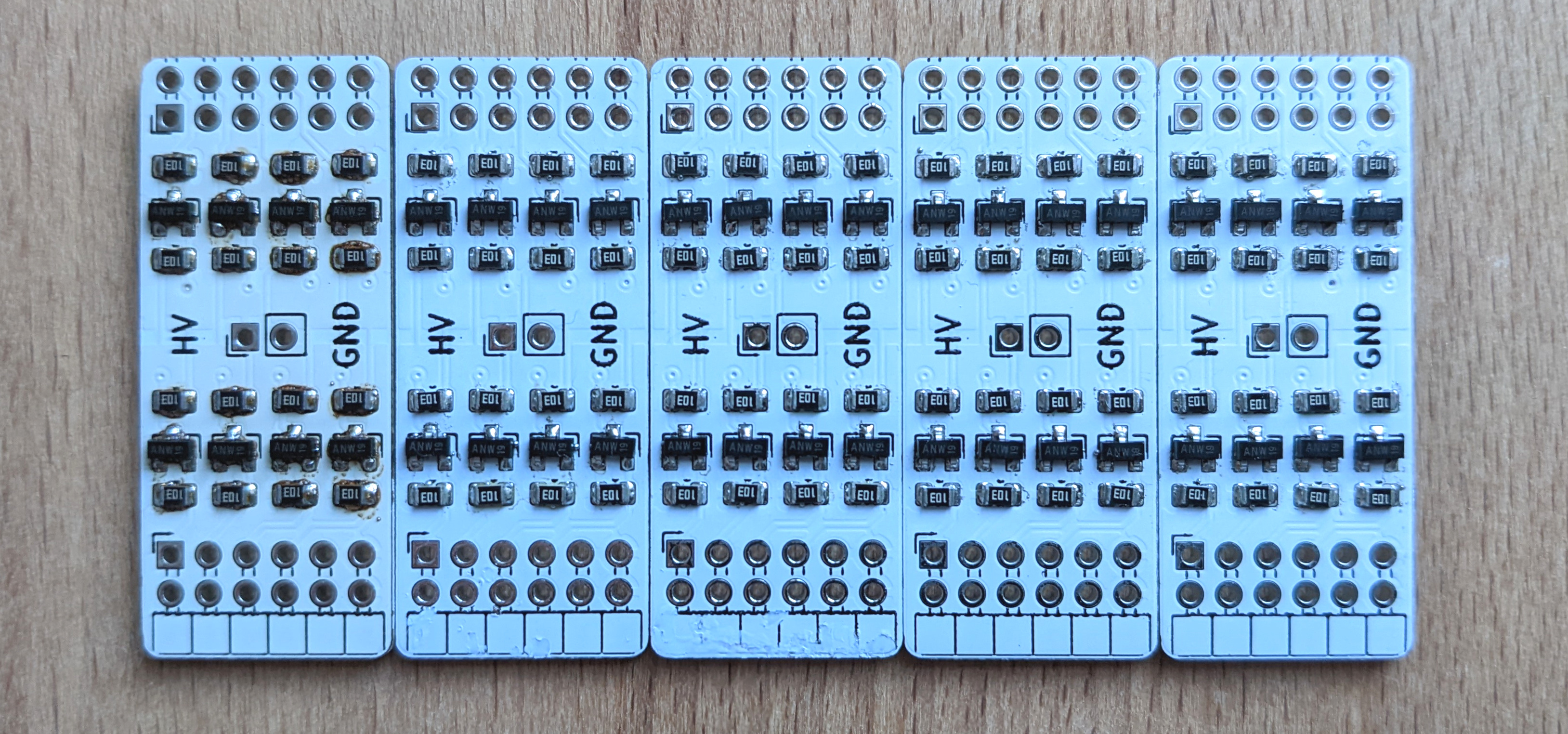
All in all it went pretty great I would say. One toasty PCB, 4 good looking ones. I don't see any solder bridges and the solder melted well on all solder joints.
Next time I will test the levelshifter using a PS/2 breakout board.